Although embedded systems have existed for several decades, only in recent times have they evolved into user-friendly technologies accessible to hobbyists without specialized knowledge. With the advent of new microcontroller architectural designs and more accessible programming languages, beginners could start using these complex systems more efficiently.
The combination of Arduino and MicroPython provides a great example: from one side, there is a famous and easy-to-use hardware platform, while from the other, a well-known programming language adapted for working on embedded systems.

In this article, I will explore how to get started with MicroPython using the Arduino Nano RP2040 Connect board.
An introduction to MicroPython
MicroPython is an efficient implementation of the Python 3 programming language designed to run on microcontrollers. The Python language is famous for its versatility and the number of pre-written code and libraries, like the MQTT Paho library, for which an extensive tutorial can be found here. MicroPython, therefore, inherits the same Python advantages.
MicroPython offers the simplicity of Python combined with the low-level control necessary for embedded development, making hardware programming more accessible, even for those with minimal experience in embedded systems.
For further information, you can check the official MicroPython website.
Why choose MicroPython for IoT projects?
MicroPython is one of the preferred choices for IoT for several reasons. The first is that MicroPython is based on Python, making it accessible to many developers, regardless of their background. This significantly reduces the learning curve for those new to embedded systems.
Second, MicroPython’s reduced footprint and efficiency are a good choice for resource-constrained microcontrollers, allowing IoT devices to function with minimal hardware resources. This is highly relevant for energy-efficient and cost-effective IoT deployments.
Finally, MicroPython’s active community and extensive library support make it easy to solve many issues that can be encountered during project development. Developers can leverage many pre-written code and modules supporting different functionalities and protocols, like the MQTT protocol, for which a very detailed guide can be found here.
In summary, MicroPython is an ideal choice for IoT projects due to its simplicity, resource efficiency, and community support.
The Arduino Nano RP2040 Connect Board
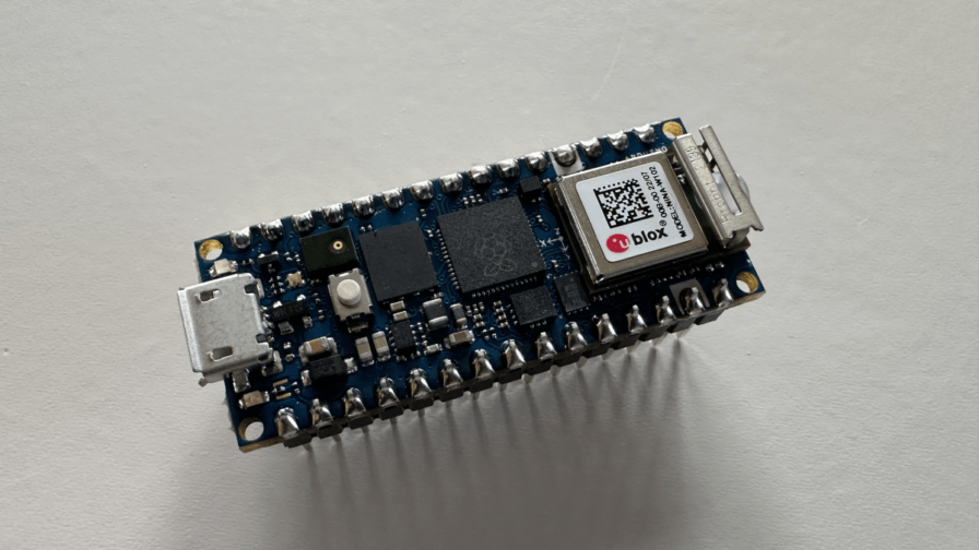
The Arduino Nano RP2040 connect is a board developed by Arduino based on the powerful and cost-effective Raspberry Pi RP2040 microcontroller (Figure 1). The RP2040 microcontroller contains a dual-core ARM Cortex-M0+ with abundant GPIOs and support for various communication interfaces.
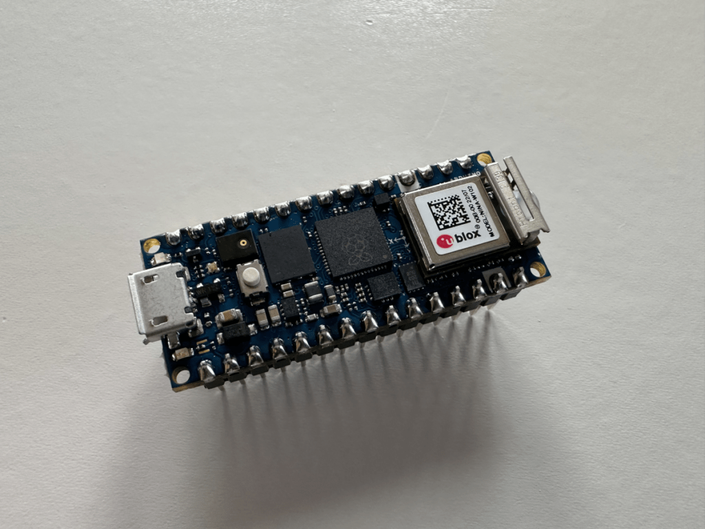
The Arduino Nano RP2040 is designed to be a compact, versatile, and easy-to-use development board. This board offers the familiar Arduino ecosystem, allowing users to program it with the classical Arduino IDE using C++ or MicroPython after a specific setup procedure, which will be illustrated in the next chapter.
This board integrates a u-blox WiFi module, making it suitable for IoT designs. WiFi connection enables the use of various communication protocols, like, for example, the well-known MQTT. If you are looking for hints on connecting multiple MQTT devices to a central broker while keeping performance under control, the following article may help you.
You can find the official page of the evaluation board at this link.
Preparing Arduino: Installing the MicroPython firmware
Installing the MicroPython firmware on the board is the first step to be performed. The Arduino RP2040 board does not natively support the MicroPython language, therefore this step is necessary.
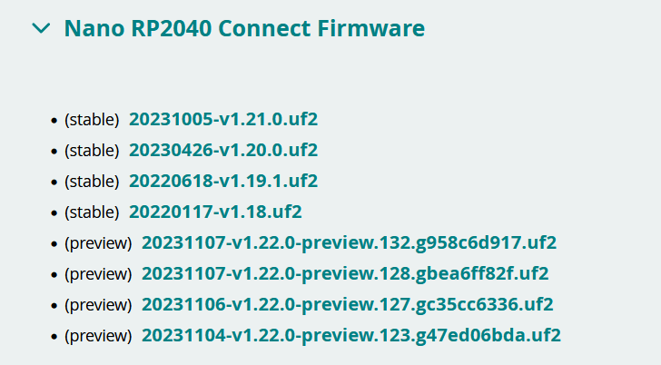
I will proceed with downloading the correct firmware from here. Different firmware are available for download, but I will choose the latest stable version (Figure 2).
Once the download is complete, I can proceed with the firmware installation.
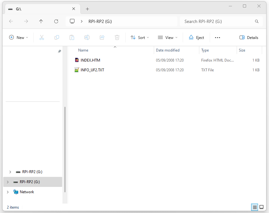
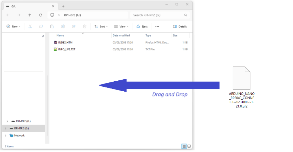
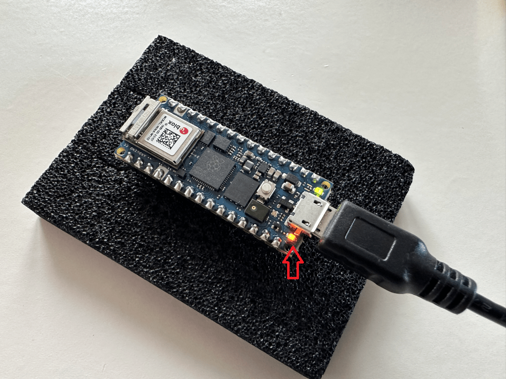
Firmware installation can be performed mainly in two ways: through a tool called Arduino MicroPython Installer or just dragging and dropping the firmware file on the board flash storage, which shows up as a mass external storage device after connecting the board to a PC through a USB Cable (Figure 3).
I will use the latter in this article, which I consider the more straightforward.
First, I will have to connect the Arduino RP2040 board to a PC using the micro USB connector from the board.
Two things can now happen:
- A mass storage device is recognized, and the relative window manager is opened. (Figure 3)
- Nothing happens.
Getting the Arduino board into the mass storage mode (also called bootloader mode) is a fundamental step for the firmware installation.
In case the mass storage does not appear, It is possible to proceed in the two following ways:
- Press the reset button two times sequentially with around 1 second between one press and the next, and if it does not work…
- Physically connect the pin REC and GND on the board and press the reset button.
One of these two ways should set the board in bootloader mode.
Once the flash storage window opens, drag and drop the previously downloaded firmware to start the installation (Figure 4).
The device is now ready to be programmed in MicroPython.
Getting the Arduino MicroPython IDE
Once the firmware has been installed, I can download the correct IDE, choosing between the two most well-known possibilities: Arduino Lab or OpenMV Editor.
The OpenMV Editor IDE was the first official MicroPython IDE supporting Arduino, providing extended functionalities for supporting computer vision operations.
Instead, Arduino Lab is a lightweight IDE for programming the classical Arduino MicroPython boards in a few steps, providing a very easy-to-use GUI.
In this article, I will use Arduino Lab, which can be downloaded here.
The downloaded zip contains the complete IDE, which does not require any installation process.
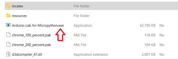
Simply extract all the content into a folder and open the application file “Arduino Lab For MicroPython.exe” (Figure 5). Once opened, the IDE window will appear. (Figure 6)
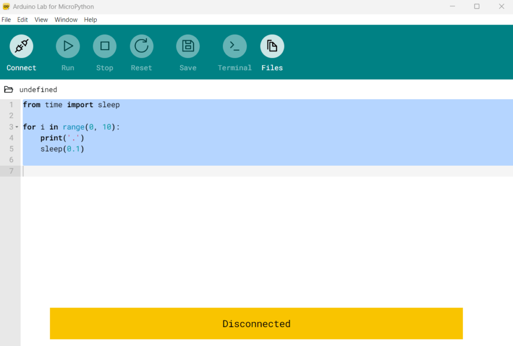
The GUI of Arduino Lab is straightforward to use, providing all the needed functionalities on the upper green bar.
In the next chapter, I will show how to write a first program and get it running on the Arduino board.
Let’s write our first MicroPython program
The first MicroPython program I will show will be a simple LED blinking. The following code can be copied in Arduino Lab.
| import time from machine import Pin # Configuring the LED Pin led = Pin(6, Pin.OUT) while (True): # Switch on the LED led.on() time.sleep_ms(500) # Switch off the LED led.off() time.sleep_ms(500) |
The code is pretty straightforward. At first, a “Pin” object is created and initialized to refer to PIN 6, which in the RP2040 board is connected to an LED.
An infinite loop is then defined, switching the LED on and off with a time interval of 500 ms.
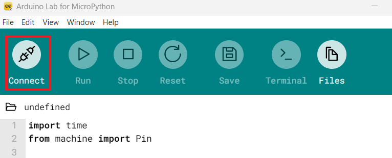
To test the code, I will first establish the connection between the Arduino board and the IDE by clicking the connect button, as shown in Figure 7.
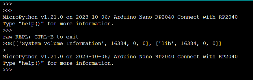
After selecting the correct COM port from the list, the following output appears in the debug window of Arduino Lab (Figure 8):
Now, click the “Run” button to start executing the code. The LED should start blinking (Figure 9).
Accessing Arduino peripherals with MicroPython
After this first LED blinking demo, I can dive deeper into the Arduino board functionalities and explore how MicroPython can effectively interact with the hardware peripherals.
Among the available peripherals, I will show a small demo on how to access the LSM6DSOX device, an IC mounted on the Nano RP2040 Arduino board, integrating an accelerometer and a gyroscope.
Accelerometers are sensors that measure acceleration, indicating the rate of change of speed of an object in a specific direction. At the same time, gyroscopes are devices that measure or maintain orientation and angular velocity, providing information about the rotation of an object.
The code example follows, which can be copy-pasted into Arduino Lab for reading the LSM6DSOX sensor values.
| import time from machine import Pin, I2C from lsm6dsox import LSM6DSOX # Configure I2C bus and initialize LSM6DSOX sensor = LSM6DSOX(I2C(0, scl=Pin(13), sda=Pin(12))) while (True): # Print accelerometer axis values print(‘Accelerometer values: x:{:<.2f} y:{:<.2f} z:{:<.2f}’.format(*sensor.accel())) # Print gyroscope axis values print(‘Gyroscope values: x:{:<.2f} y:{:<.2f} z:{:<.2f}’.format(*sensor.gyro())) print(“”) time.sleep_ms(500) |
A specific LSM6DSOX library is already provided and integrated into the Arduino Lab environment, allowing the accelerometer and gyroscope data to be easily obtained.
The sensor values are read through the I2C bus, accessed through pins 12 and 13, as shown in the code snippet.
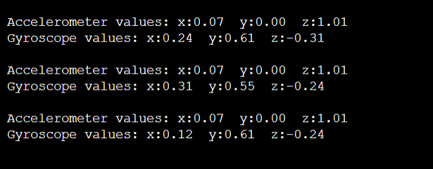
The sensor reading is performed in an infinite loop cycle using the object’s methods “accel()” and “gyro()”. The sensor values are then printed on the output console.
Let’s copy the code into the Arduino Lab IDE and download it into the Arduino Board. The following output is shown in the debug console, demonstrating the successful reading of the sensor values.
Conclusions
In conclusion, programming the Arduino Nano RP2040 with MicroPython opens up a world of possibilities for developers seeking a flexible and efficient microcontroller experience. Integrating MicroPython with the powerful RP2040 chip simplifies the development process, making it accessible even for those new to embedded systems. With its rich ecosystem of libraries and the familiar Python syntax, the Arduino Nano RP2040 can become a versatile tool for various projects, from IoT applications to robotics.